
Art-Net
The following information is condensed from https://en.wikipedia.org/wiki/DMX512
DMX512 is a standard for digital communication networks that are commonly used to control lighting and effects. It was originally intended as a standardized method for controlling stage lighting dimmers, which, prior to DMX512, had employed various incompatible proprietary protocols. It quickly became the primary method for linking controllers (such as a lighting console) to dimmers and special effects devices such as fog machines and intelligent lights.
The DMX512 standard (for Digital Multiplex with 512 pieces of information) was created in 1986, with subsequent revisions in 1990 leading to USITT DMX512/1990.
DMX512 has also expanded to uses in non-theatrical interior and architectural lighting, at scales ranging from strings of Christmas lights to electronic billboards and stadium or arena concerts. It can now be used to control almost anything, reflecting its popularity in all types of venues.
A maximum-sized packet, which has 512 channels (slots following the start code), takes approximately 23 ms to send, corresponding to a maximum refresh rate of about 44 Hz. For higher refresh rates, packets having fewer than 512 channels can be sent. Generally it is recommended to work with a lower refresh rate like 30 Hz.
DMX512 does not include automatic error checking and correction, and therefore is not an appropriate control for hazardous applications, such as pyrotechnics or movement of theatrical rigging. However, it is still used for such applications. False triggering may be caused by electromagnetic interference, static electricity discharges, improper cable termination, excessively long cables, or poor quality cables.
8-bit v. 16-bit
Many parameters of moving lights make use of encoding larger than 8 bit numbers. To control these parameters more accurately, some fixtures use two channels for parameters that require greater accuracy. The first of the two channels controls the coarse (256 steps for the whole range of movement) and the second the fine (256 steps for each coarse step), this gives a 16-bit value range of 65536 steps, permitting much greater accuracy for any 16-bit controlled parameter such as Pan or Tilt.
Network topology
A DMX512 network employs a multi-drop bus topology with nodes strung together in what is commonly called a daisy chain. A network consists of a single DMX512 controller – which is the master of the network — and one or more slave devices. For example, a lighting console is frequently employed as the controller for a network of slave devices such as dimmers, fog machines and intelligent lights.
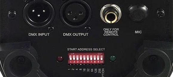
Each slave device has a DMX512 “IN” connector and usually an “OUT” (or “THRU”) connector as well.
The controller, which usually has only an OUT connector, is connected via a DMX512 cable to the IN connector of the first slave.
A second cable then links the OUT or THRU connector of the first slave to the IN connector of the next slave in the chain, and so on. For example, the block diagram below shows a simple network consisting of a controller and three slaves.
The specification requires a ‘terminator’ to be connected to the final OUT or THRU connector of the last slave on the daisy chain, which would otherwise be unconnected. A terminator is a stand-alone male connector with an integral 120 Ω resistor connected across the primary data signal pair; this resistor matches the cable’s characteristic impedance. If a secondary data pair is used, a termination resistor is connected across it as well.
Although simple systems (i.e., systems having few devices and short cables) will sometimes function normally without a terminator, the standard requires its use. Some DMX slave devices have built-in terminators that can be manually activated with a mechanical switch or by software, or by automatically sensing the absence of a connected cable.
Connectors
The original DMX512 1990 specified that where connectors are used, the data link shall use five-pin XLR style electrical connectors (XLR-5), with female connectors used on transmitting (OUT) ports and male connectors on receiving ports.

The three-pin XLR connector is commonly used for DMX512, on lighting and related control equipment, particularly at the budget/DJ end of the market. However, using three-pin XLR connectors for DMX512 is specifically prohibited by section 7.1.2 of the DMX512 standard.
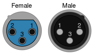
Use of the three-pin XLR in this context firstly presents a risk of damage to the lighting equipment should an audio cable carrying 48 volt phantom power be accidentally connected, and secondly encourages the use of cable following analogue audio specifications for DMX, which can lead to signal degradation and unreliable operation of the DMX network.
Cabling
The standard cables used in DMX512 networks employ XLR5 connectors, with a male connector on one end and a female connector on the other end. The cable’s male connector attaches to the transmitting, female jack (OUT), and its female connector attaches to the receiving, male jack (IN).
Cat5 cable, commonly used for networking and telecommunications, has been tested by ESTA for use with DMX512A.
Microphone and line level audio cables lack the requisite electrical characteristics and thus are not suitable for DMX512 cabling. The significantly lower impedance and higher capacitance of these cables distort the DMX512 digital waveforms, which in turn can cause irregular operation or intermittent errors that are difficult to identify and correct.
Universes
A DMX512 network is called a “DMX universe”.
Each OUT connector on a DMX512 controller can control a single universe.
A DMX512 universe is made up of 512 channels,
with each channel containing a value between 0 and 255.
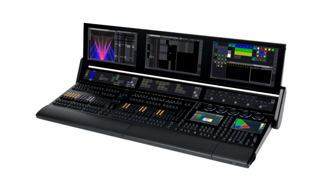
Each slave device in the chain can “look at” a different set of channels in order to be controlled by the master controller. Smaller controllers may have a single OUT connector, enabling them to control only one universe, whereas large control desks (operator consoles) may have the capacity to control multiple universes, with an OUT connector provided for each universe.
Adressing
As all devices in a universe are daisy chained and essentially receive the same data, they have to be told, which part of that data is ment for them. This is done by giving each device a start adress, telling it wich is the first channel that is relevant to them. Then the device will use as many channels as it needs and the next free channel is the starting adress for the next device.
So let’s say you have an RBG spot, that in the most simple case will use three channels for setting the R,G and B values and it has a starting adress of 4 (because another RGB spot is chained before it), the this spot will listen to channels 4,5,6 and the next device can start at channel 7.
In older devices the starting address was configured through “jumpers”. This looks very kryptic (and to me it is), but there are mobile apps that help you with that. If you want to explore, you can use this online tool:
https://www.laserworld.com/en/laserworld-toolbox/dmx-address-setting.html
A bigger DMX network is structured into universes, nets and subnets. This is just terminology and shouldn’t scare us. It has nothing to to with actual networking.
Universes : 0-15 = 16
Nets : 0-127 = 128
Subnets : 0-15 = 16
16 * 128 * 16 = 32768 Universes
Wireless operation
Recently, wireless DMX512 adapters have become popular, especially in architectural lighting installations where cable lengths can be prohibitively long. Such networks typically employ a wireless transmitter at the controller, with strategically placed receivers near the fixtures to convert the wireless signal back to conventional DMX512 wired network signals.
Multiple incompatible wireless protocols currently exist. While DMX-over-Ethernet protocols such as Streaming ACN can be used to send DMX data over WiFi, this is not generally recommended due to the highly variable latency of WiFi.